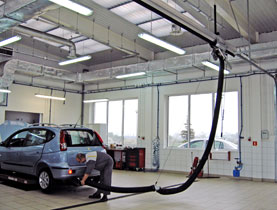
Application
Self-tightening suction duct KOS-AL is applied for removal the vehicle
exhaust fume by means of mobile balancing extractor
OBP-AL (or a
mobile extractor OP-AL) which is moving along the duct. The trolley is
displacing along the duct while vehicle is pulling the hose with nozzle
(coupled at the vehicle’s exhaust pipe). The duct is applied to serve cars and lorries.
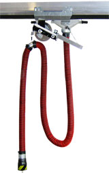
Structure
The KOS-AL duct is constructed of aluminium segments of length 13
feet joined together to the requested length depending on User’s
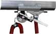
needs. The trolley’s fitting piece is sliding in a slot between 2 rubber
aprons. The underpressure formed by extraction fan seals the aprons
together. The OBP-AL extractor is equipped with a balancer (to lift the
hose), locking pawl fixing the hose at a required work-length and a
nozzle.
In application with a the self-release nozzle – the releaser disconnects
the nozzle automatically, while the extraction trolley approaches the
duct-end. After disconnection, the hose with nozzle is lifted to its
home position.
Whereas, in application with a nozzle without self-releaser – it should
be disconnected manually and then pulled slightly to start the balancer
for lifting.
Terminal stoppers (fixed at the duct-ends) – are slowing down the
trolley speed, while it approaches the duct-ends. The recommended
height of duct mounting is 10 to 13 feet (above the floor surface).
This application gives a possibility to connect the duct with the discharge
system at both ends of the duct or on its upper surface.
Self-tightening suction duct
 |
Type |
Part # |
Segment length
[ft] |
Cross section
[sq. in] |
Unit weight
[lb/ft] |
| KOS-AL |
804K05 |
13 |
45 |
6.5 |
Mobile balancing extractor
 |
Type |
Part # |
Hose
diameter
[in] |
Hose length [ft] |
Recomm.
flow
capacity
[cfm] |
Flow
resistance
[in. w.g] |
Weight
[lb] |
| OBP-AL-100-6 |
804O21 |
4 |
20 |
250 |
4.8 |
79 |
| OBP-AL-125-6 |
804O22 |
5 |
20 |
400 |
5.2 |
81 |
| OBP-AL-150-6 |
804O23 |
6 |
20 |
900 |
8.0 |
83 |
Mobile extractor – without balancer – hose should be lifted manually, the hose length is unlimited
| Type |
Part # |
Hose
diameter
[in] |
Hose length [ft] |
Recomm.
flow
capacity
[cfm] |
Flow
resistance
[in. w.g] |
Weight [lb] |
| OP-AL-100-6 |
804O35 |
4 |
20 |
250 |
4.0 |
26 |
| OP-AL-125-6 |
OP-AL-125-6 |
5 |
20 |
400 |
4.4 |
28 |
| OP-AL-150-6 |
OP-AL-150-6 |
6 |
20 |
900 |
7.2 |
30 |
Connectors*
| Sort of the fitting piece |
Type |
Part # |
Diameter [in] |
 |
for axial
connection |
KPC |
804K20 |
6 |
 |
for upper
connection |
KPG |
804K25 |
8 |
* To connect the duct КОS-АL with the discharge ductwork.
Duct hangers
| Sort of the hanger |
Type |
Part # |
Description |
 |
ceiling hanger |
Z |
804K29 |
The hangers
are fixed to the duct
by
bolting.
The spacing between the hangers should
not exceed
10 feet. |
 |
wall hanger |
L |
804K27 |
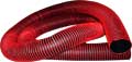
Hose
 |
Type |
Part # |
Diameter
[in] |
Thermal
resistance
[F] |
Remarks |
G-EX1-100
G-EX1-125
G-EX1-150 |
328P60
328P6
328P62 |
4
5
6 |
302 |
Material: black
impregnated polyester
cloth with spiral; light
weight, flexible, resistant
against constant
squeezing. |
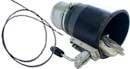
Nozzles
Sort of
nozzle |
Type |
Part # |
Connection
diameter
[in] |
Inlet size
[in] |
Weight
[lb] |
Remarks |
 |
SZGO-125 SZGO-150 |
819S28
819S29 |
5
6 |
6
6.7 |
5.5
7.1 |
Circular rubber
with
clamping
mechanism. |
 |
SZGP-100
SZGP-125 |
819S18
819S19
|
4
5 |
7.1 × 4
8.7 × 6 |
4.6
7.1 |
Oval rubber
with clamping
mechanism. |
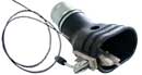
|
SZGO-125/B
SZGO-150/B |
819S70
819S71 |
5
6 |
6
6.7 |
5.5
7.1 |
Circular rubber
with
clamping
mechanism;
automatic disconnection
by Bowden cable. |
 |
SZGP-100/B
SZGP-125/B |
819S72
819S73 |
4
5 |
7.1 × 3.9
8.7 × 5.9 |
4.6
7.1 |
Oval rubber with clamping
mechanism; automatic
disconnection by
Bowden
cable. |
NOTE: Placing the order specify the part № and type designation of the given device.
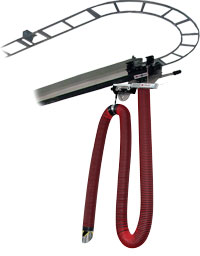
Return rail suction duct
The return rail and special construction of extraction trolley assures a simultaneous
constant service of several cars in one row,
in distance from entrance door to the exit
of the garage. At the moment when the
vehicle is leaving the garage – the selfreleasing
mechanism is disconnecting the
nozzle and the released extraction trolley
stops its movement on the rail-arc. From
this point the trolley is being displaced the
way back on the return-rail and is ready to
be connected to the next serviced vehicle.
This type of solution we are executing on
individual demand. |
 |